 ar
ar bg
bg hr
hr cs
cs da
da nl
nl fi
fi fr
fr de
de el
el hi
hi it
it ko
ko no
no pl
pl pt
pt ro
ro ru
ru es
es sv
sv tl
tl iw
iw id
id lv
lv lt
lt sr
sr sk
sk sl
sl uk
uk vi
vi et
et hu
hu th
th tr
tr fa
fa ms
ms hy
hy ka
ka ur
ur bn
bn mn
mn ta
ta kk
kk uz
uz ku
ku
load cell wiring diagram
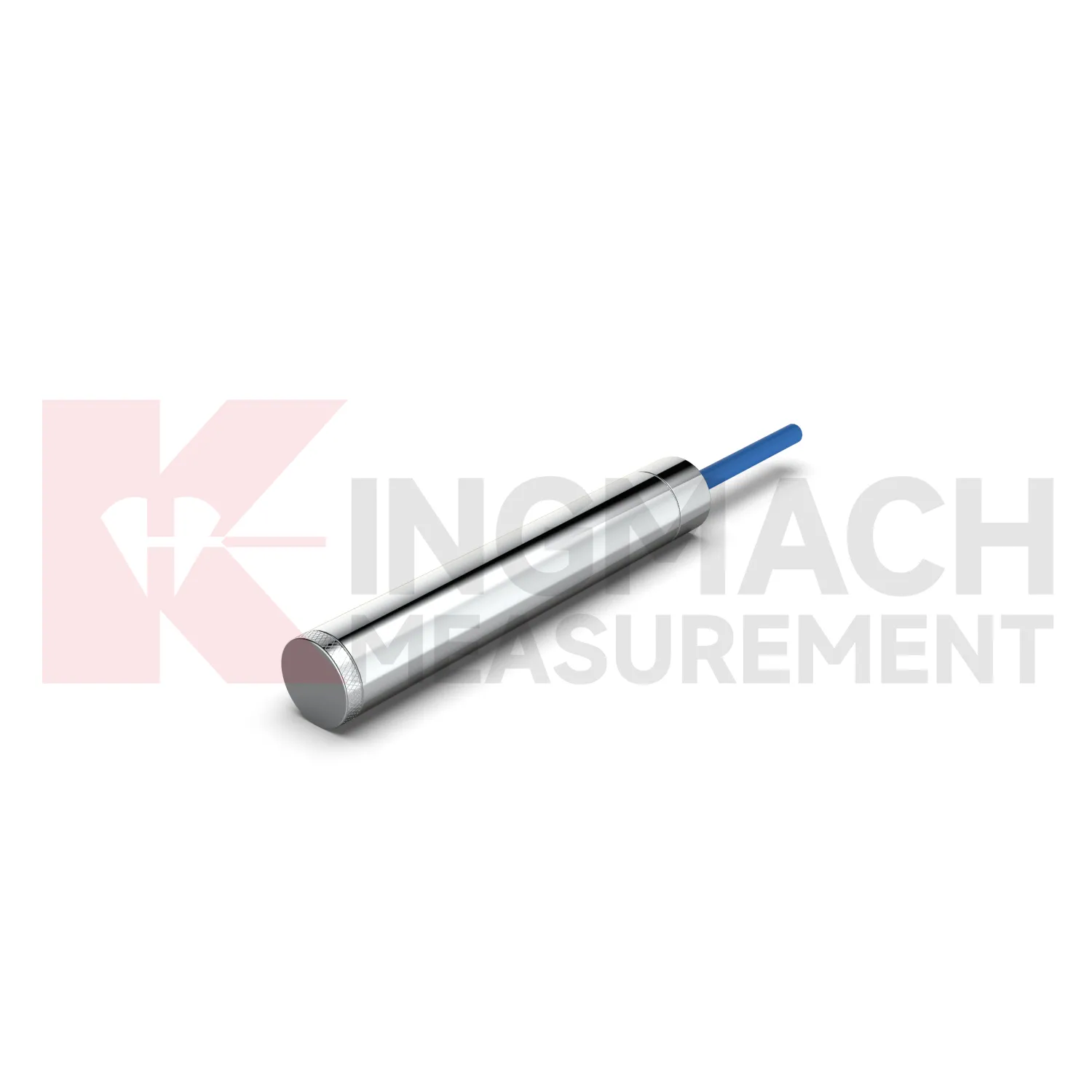
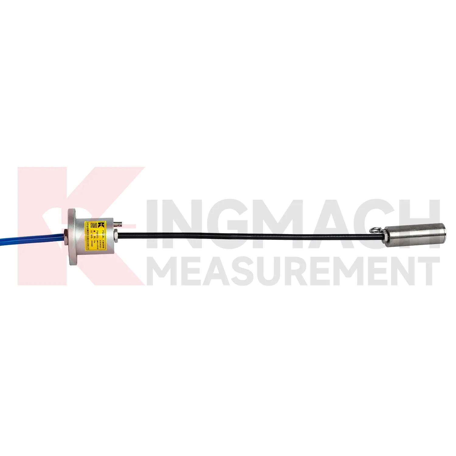
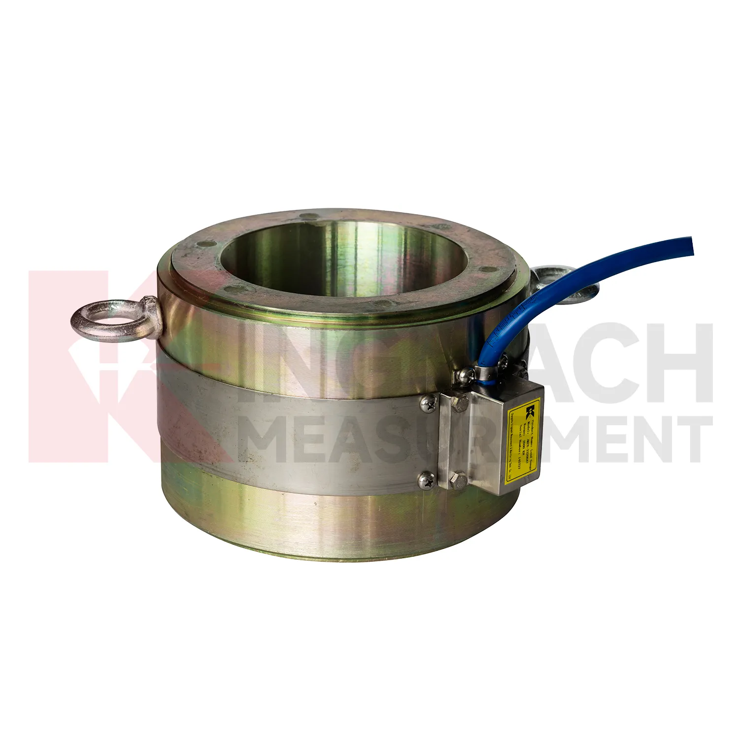
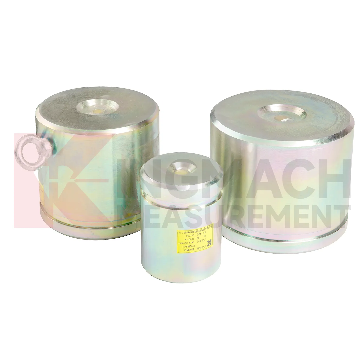
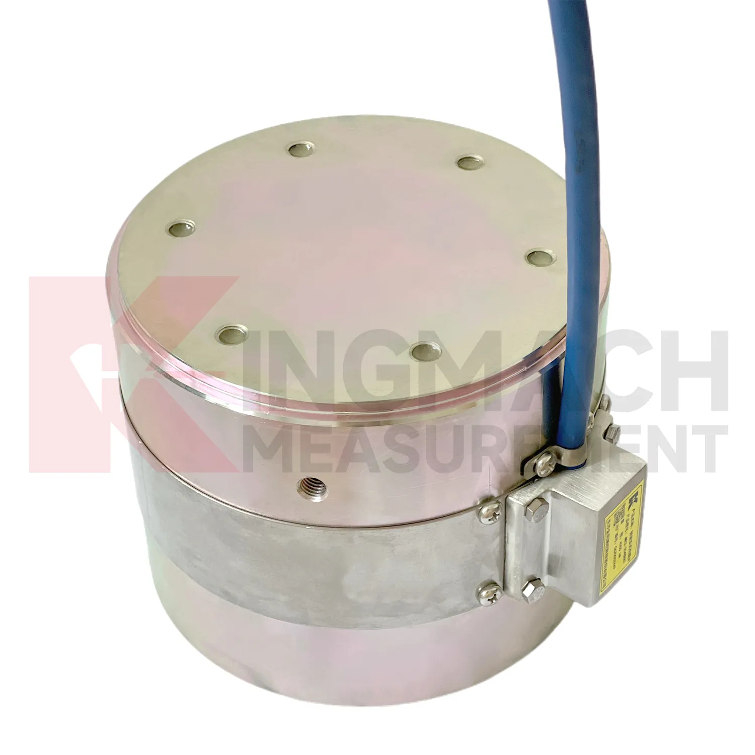
Kingmach load cell wiring diagram descriptions should be read together with the data chain around the sensor. A hollow load cell can cover 500 kN to 8000 kN with a long service design, while the solid load cell line reaches 10000 kN with 0.5%FS precision. The axial force meter adds direct kN display and a 1 MPa waterproof rating for support load monitoring. Smart models include memory for calibration information, zero values, temperature data, and stored measurement records. These are not decorative features. They reduce uncertainty when many sensors are installed across a bridge, tunnel, foundation pit, dam, or rail project. Kingmach supplies readouts and data acquisition equipment, so a single instrument can be used for manual reading during installation and later connected to centralized monitoring if the owner requires it. The better specification path starts with the monitored member, expected load range, access condition, waterproof exposure, temperature swing, cable distance, and reporting method, then selects the model around those constraints. Kingmach's after-sales information also refers to warranty service, anti-static and shockproof packaging, and technical response support. Those points are useful in force monitoring because sensor damage, delivery handling, and setup questions can all affect whether the first readings are trusted.
Application of load cell wiring diagram
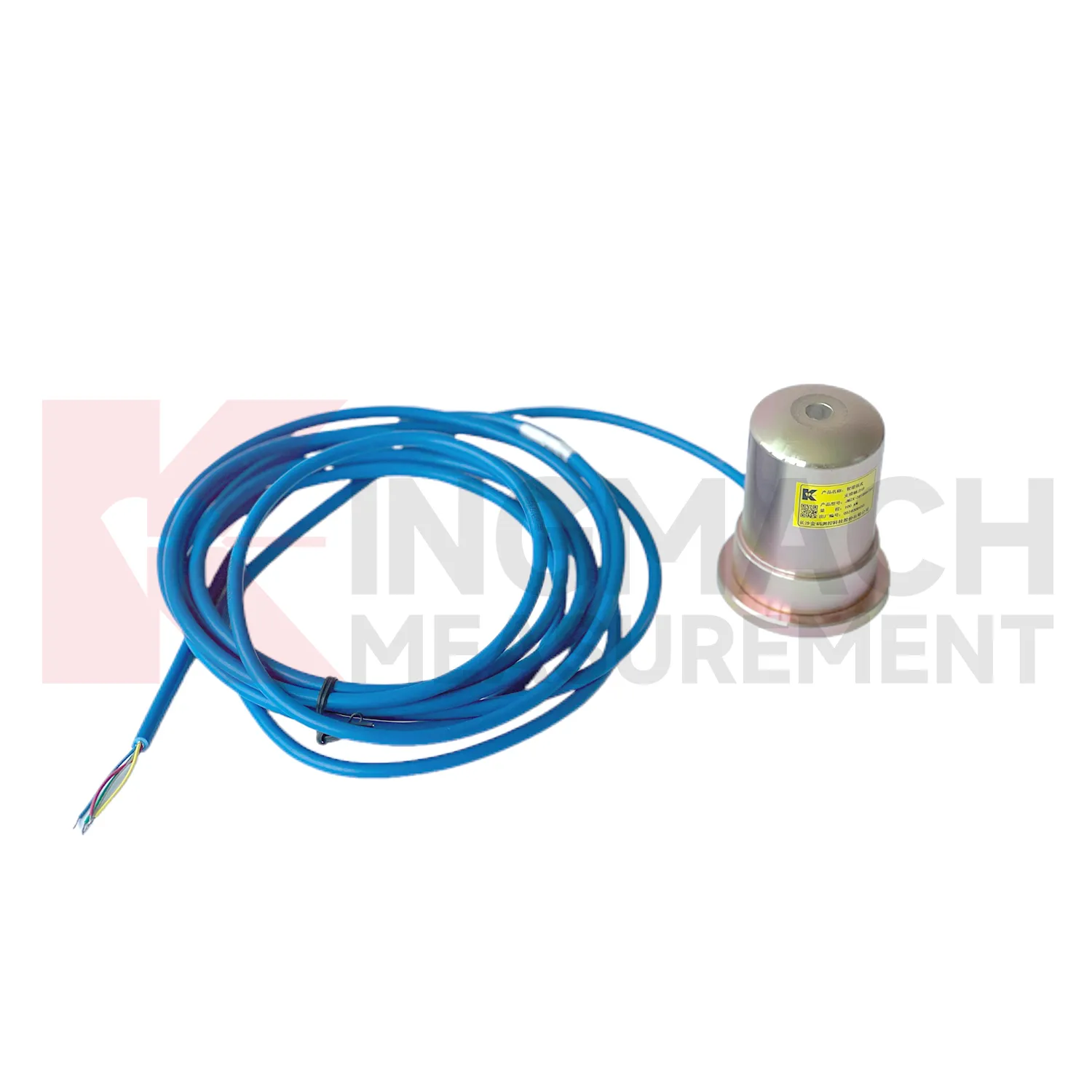
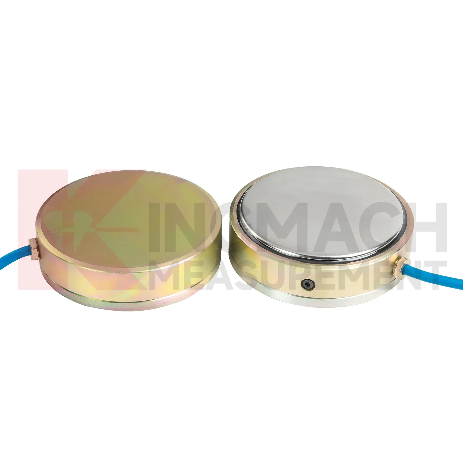
In foundation pit projects, load cell wiring diagram supports strut force monitoring, anchor load control, retaining wall pressure checks, and load transfer review as soil is removed. The painful part of this work is timing: force can rise quickly after excavation, rainfall, dewatering, or support adjustment, while the working area is still changing every day. The axial force meter JMZX-38XXHAT covers 200 kN to 3000 kN and provides 0.5%FS accuracy with direct kN display. For soil pressure at retaining structures, the JMZX-50XXAT/ATM earth pressure cell line covers 0.3 MPa to 8 MPa with 0.001 MPa resolution and 0.5%FS pressure accuracy. These numbers give the monitoring team enough detail to track staged construction rather than only final condition. Good use also depends on bearing plates, adequate surface strength, cable protection, waterproof connectors, and a reading plan after each excavation layer. The force record should be compared with settlement, horizontal displacement, water pressure, and nearby construction notes. If automated monitoring is used, alarm thresholds should be tied to excavation stages rather than copied across all channels. A strut close to the active excavation face may behave differently from one several levels above, even when the same instrument model is used.
The future of load cell wiring diagram
The next stage for load cell wiring diagram in infrastructure monitoring is tighter integration with site data systems. Smart sensors already store model data, calibration coefficients, zero values, temperature readings, and measurement records on selected Kingmach products. The practical path is to connect that identity data with 4G, LoRa, wired acquisition, or 5G gateways, then place the force trend beside displacement, settlement, pore pressure, and rainfall in the same review screen. This matters because future warnings will be less about one limit value and more about patterns: force rising after excavation, anchor load falling after heavy rain, or bridge cable force drifting during seasonal temperature cycles. Digital twin models can use those readings when the sensor location, range, and calibration background are reliable. Standards and owner specifications for structural health monitoring are also becoming more data traceability focused, which favors instruments that can carry their own calibration identity and remain readable through long service periods.
Care & Maintenance of load cell wiring diagram
For load cell wiring diagram used with manual readouts, care depends on repeatable procedure. Before installation, store the calibration sheet with the instrument and confirm that the readout supports the sensor type. Kingmach product pages mention compatible readouts and comprehensive vibrating wire instruments, which can display force values directly on selected models. During installation, label the cable and channel clearly, record the zero value, and protect the connection point from water and pulling. During each reading round, use the same unit, readout setting, point name, and observation sequence. Note temperature, weather, construction activity, and any visible damage near the sensor. Long term maintenance should include connector cleaning, cable jacket inspection, comparison with nearby points, and periodic calibration planning according to project requirements. If a reading seems wrong, repeat it after checking the cable and readout battery. Many apparent sensor faults come from swapped channels, loose connectors, or missing zero records. Use the same readout settings.
Kingmach load cell wiring diagram
load cell wiring diagram can be treated as a field witness for hidden force transfer in civil structures. Concrete, steel, soil, cable systems, and hydraulic loading may all look calm while the internal load path changes. Kingmach products in this category cover hollow load cells for anchors and cables, solid load cells for compression and pile testing, axial force meters for steel support loads, and earth pressure cells for contact pressure. Each type answers a different site question. Has the anchor lost tension? Is a pile test load centered? Is an excavation support taking more force after the next soil layer is removed? Is water pressure pushing the retaining structure harder after rain? The strongest monitoring records combine the sensor model, calibrated coefficient, zero value, temperature, reading time, and construction stage. That record gives owners a way to compare today with last week, last season, or the previous loading step, instead of relying on a single inspection note.
FAQ
Q: Can load cell wiring diagram be used for soil pressure or retaining wall pressure? A: Yes, pressure related models such as earth pressure cells are used where the measured value is contact pressure rather than direct member force. Q: What ranges are listed for Kingmach earth pressure cells? A: The JMZX-50XXAT/ATM family lists 0.3 MPa, 0.6 MPa, 1 MPa, 2 MPa, 4 MPa, 6 MPa, and 8 MPa ranges. Q: What accuracy and resolution are listed? A: The product file gives 0.001 MPa pressure resolution, 0.5%FS pressure accuracy, and ±0.5°C temperature accuracy. Q: Where are these readings useful? A: Foundation pits, dams, slopes, retaining walls, embankments, tunnels, and buried structures. Q: What maintenance issue is most common? A: Cable damage, water entry, channel confusion, and poor installation records cause many field doubts.
Reviews
Daniel Brown
Excellent environmental monitoring sensors. The data is consistent, and the system integrates smoothly with our existing setup.
Ryan Lewis
Fast delivery and excellent product quality. The accelerometers and tiltmeters are highly reliable. Strongly recommend this company.
Latest Inquiries
To protect the privacy of our buyers, only public service email domains like Gmail, Yahoo, and MSN will be displayed. Additionally, only a limited portion of the inquiry content will be shown.
Harper***@gmail.comIndia
Dear Sir, we are planning to procure a complete monitoring system including strain gauges, tiltmeter...
Sophia***@gmail.comUnited Kingdom
Good day, we need environmental monitoring sensors including temperature, humidity, and wind sensors...