
 EN
EN
 ar
ar bg
bg hr
hr cs
cs da
da nl
nl fi
fi fr
fr de
de el
el hi
hi it
it ko
ko no
no pl
pl pt
pt ro
ro ru
ru es
es sv
sv tl
tl iw
iw id
id lv
lv lt
lt sr
sr sk
sk sl
sl uk
uk vi
vi et
et hu
hu th
th tr
tr fa
fa ms
ms hy
hy ka
ka ur
ur bn
bn mn
mn ta
ta kk
kk uz
uz ku
ku
load cell cable
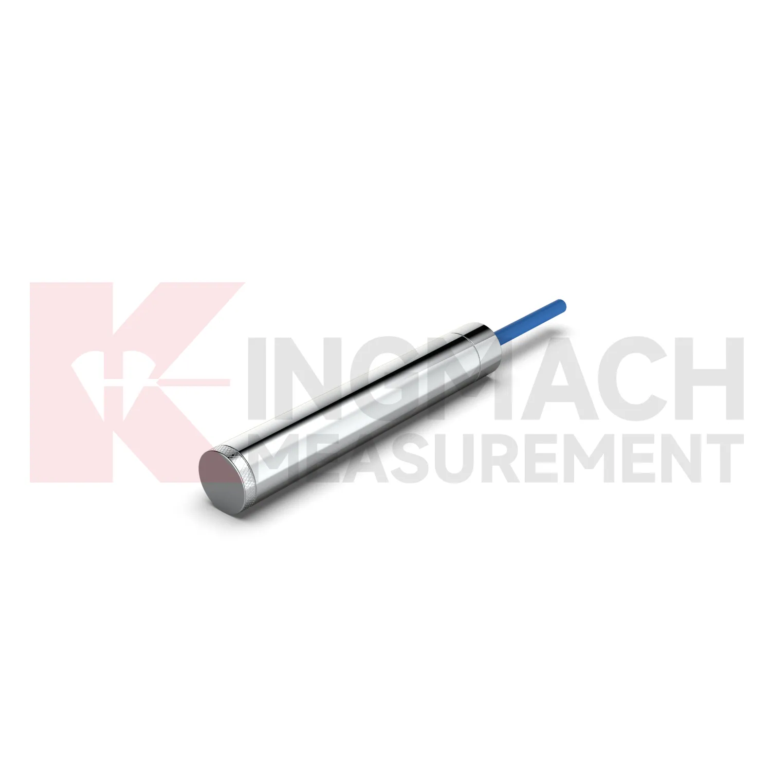
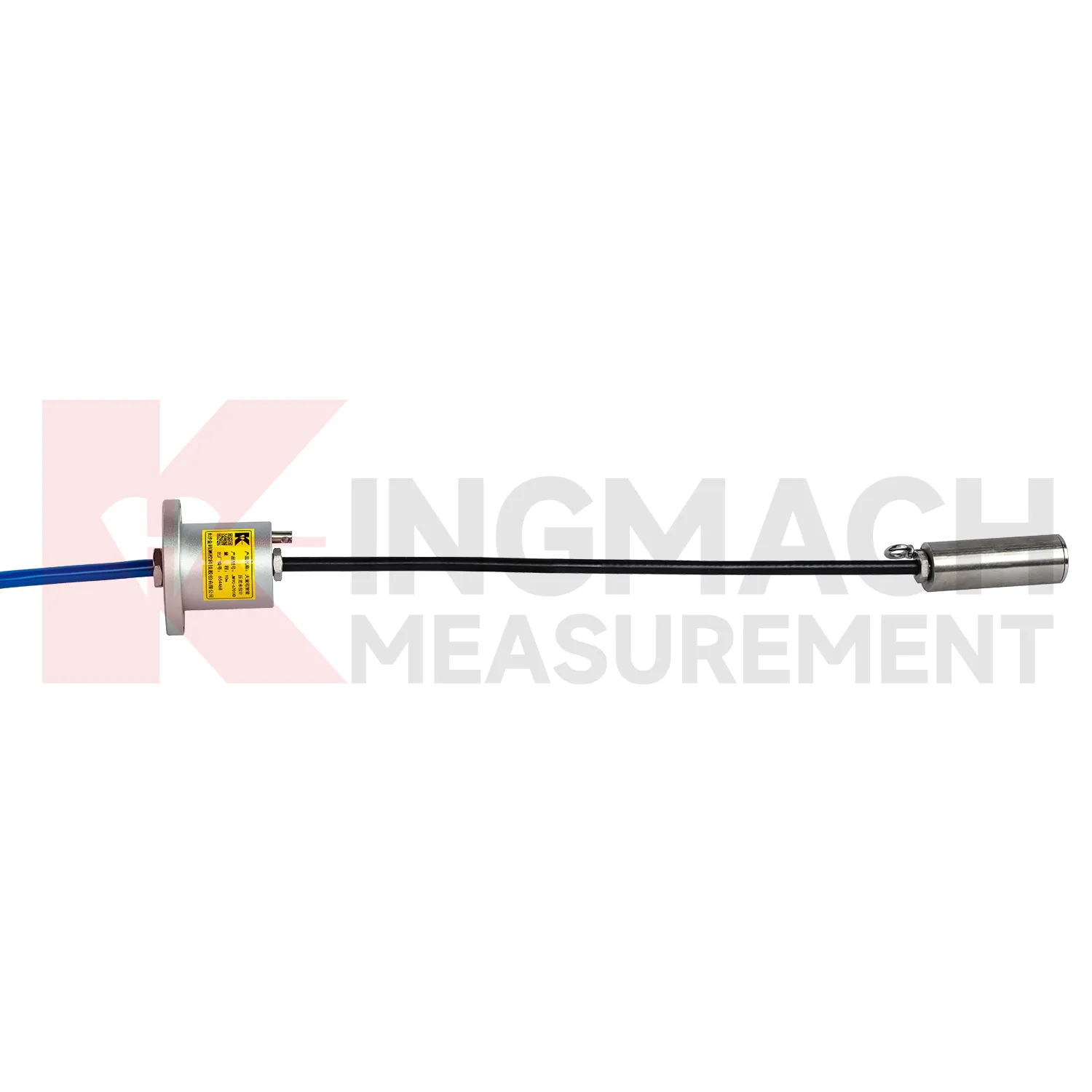
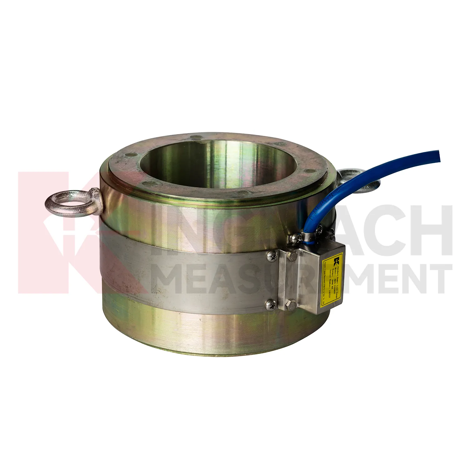
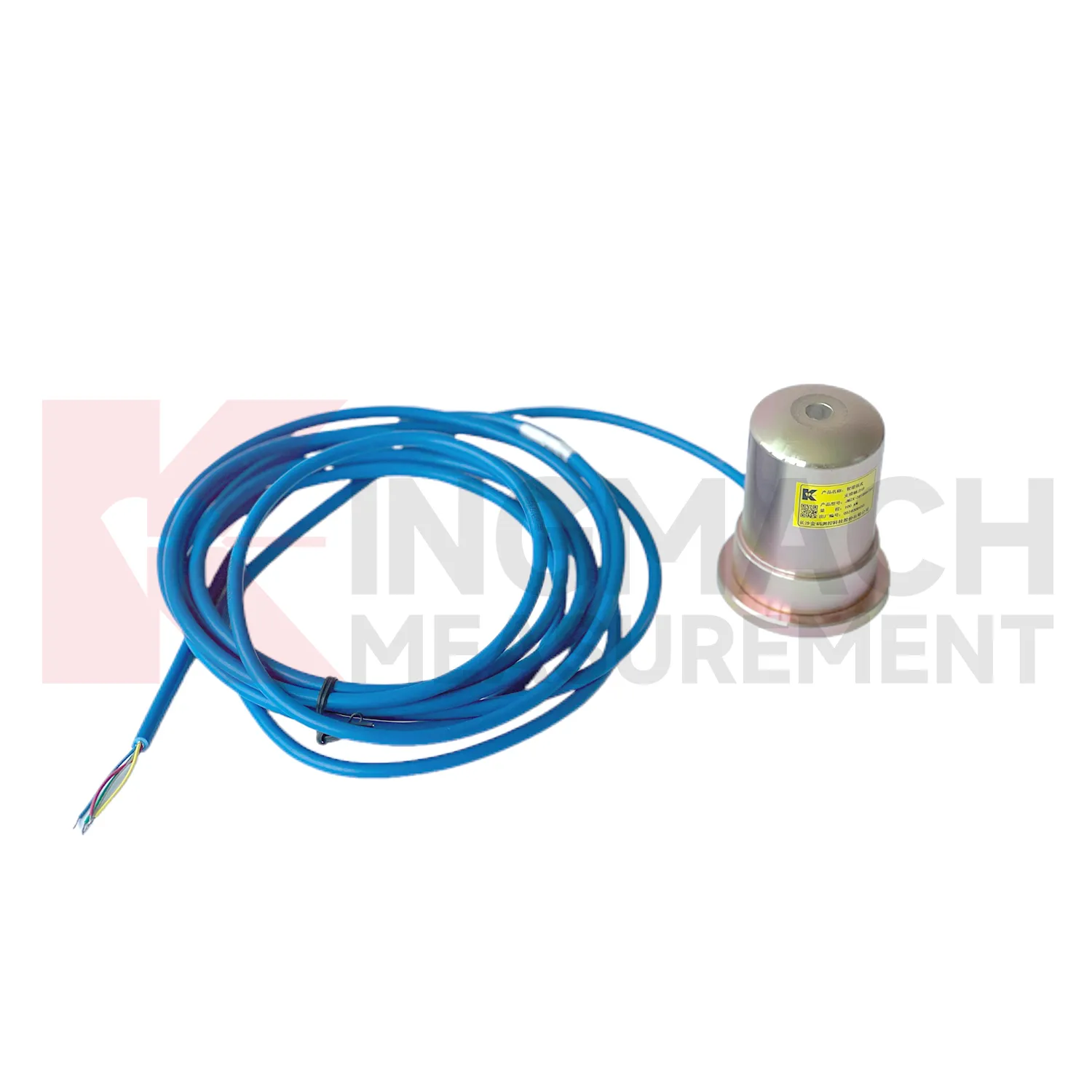
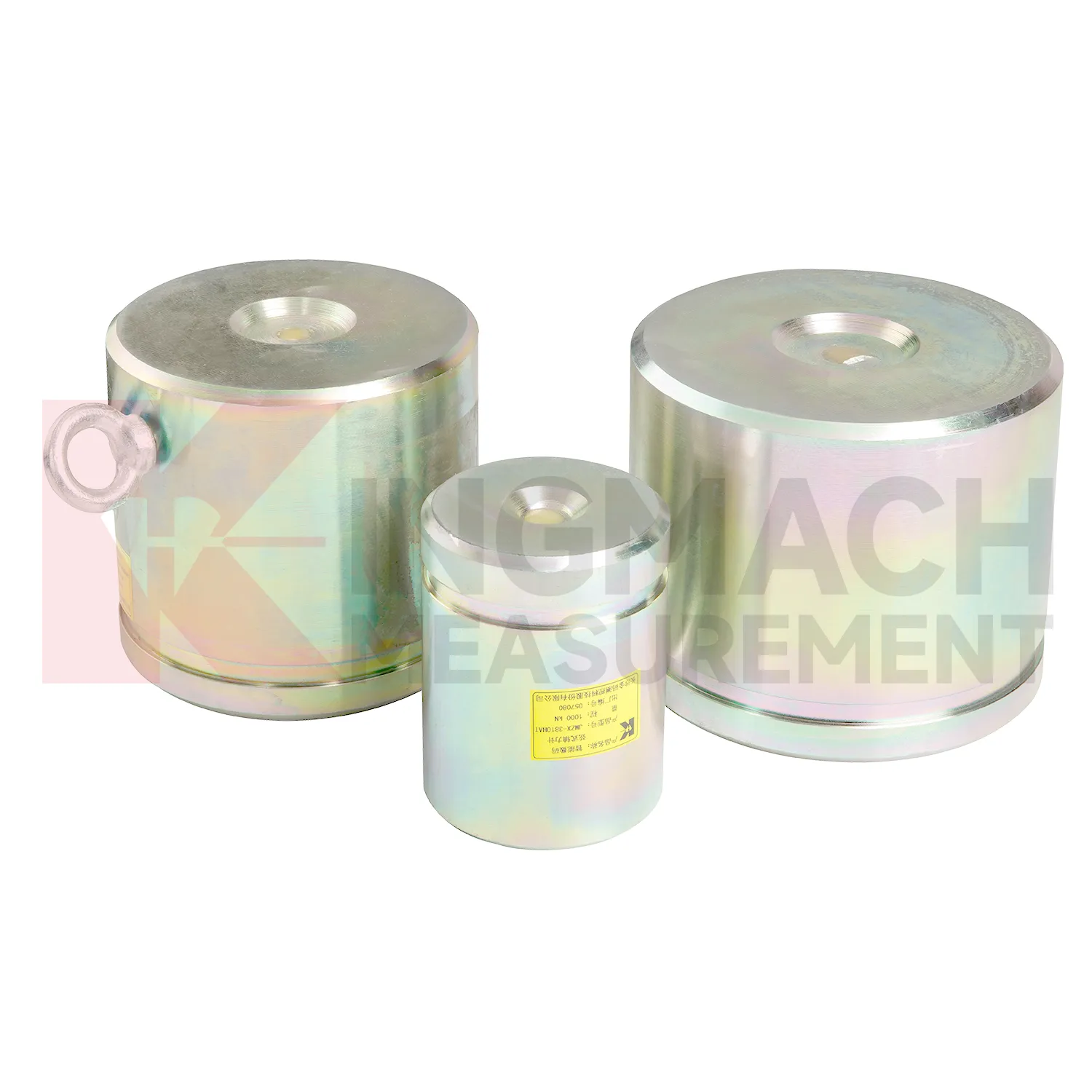
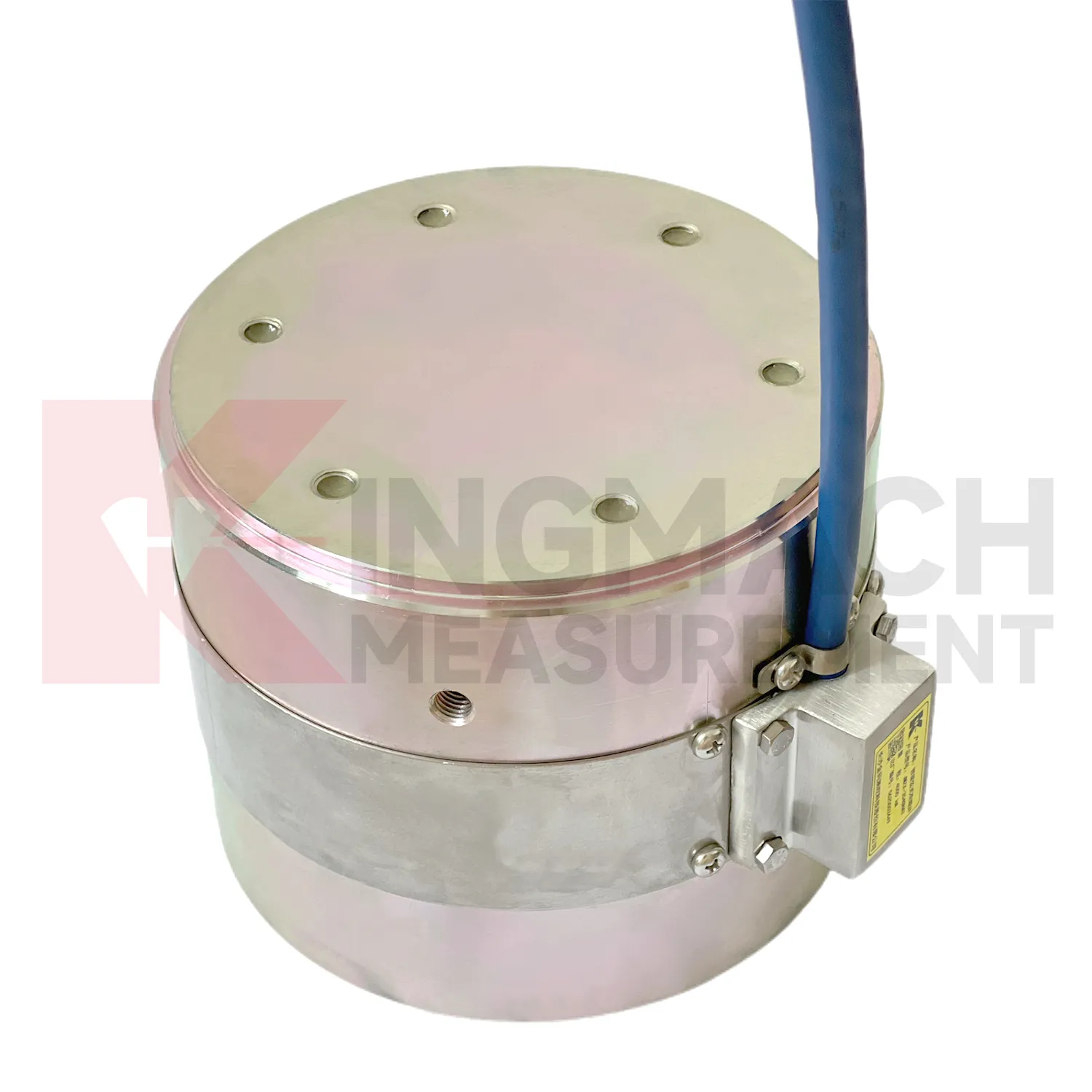
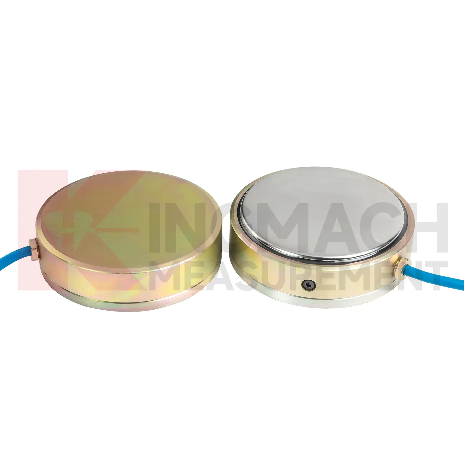
Kingmach load cell cable is suitable for projects that need both high capacity and traceable readings. The solid JMZX-35XXHAT line lists a 0.5%FS precision rating, a -30°C to 80°C temperature range, and overload information up to 20 to 50%F.S. for range overload and 300 to 400%F.S. for failure overload. The hollow JMZX-3XXXHAT line lists a 50 year design life, waterproof durability, digital output, and storage for 800 measurement records. The axial force JMZX-38XXHAT line lists 1 MPa waterproofing and direct kN display. Together, these points support force measurement in bridges, buildings, railways, transportation, hydropower, dams, tunnels, and foundation pits. Kingmach also provides monitoring products beyond load measurement, allowing the force record to be compared with movement, pressure, and environmental data. That is useful when a load change needs to be judged against the wider behavior of the structure rather than treated as a disconnected alarm. Kingmach's product pages also refer to industry certifications such as GB/T 13606-2007 and DL/T 269-2022 on selected models. Such references help buyers request documentation that matches project acceptance procedures and owner audit needs. This helps avoid ordering a sensor that is strong enough on paper but difficult to seat, wire, read, or protect in the actual structure.
Application of load cell cable
In pile load testing and bearing capacity verification, load cell cable helps track applied force, load stages, unloading response, and residual behavior. The common problem is uncertainty around whether the applied load is centered and whether the recorded value matches the actual force passing through the test system. Kingmach solid load cells such as JMZX-35XXHAT list 1000 kN to 10000 kN ranges, 0.1 kN resolution, and 0.5%FS precision, with overload information listed as 20 to 50%F.S. range overload and 300 to 400%F.S. failure overload. These figures suit heavy test work when capacity margin must be checked before the sensor is installed. During the test, the record should include each loading step, hold time, unloading step, zero check, temperature, and any change to the bearing arrangement. Pairing the load record with settlement readings gives a clearer view of pile response. After the test, the documented calibration coefficient and instrument identity help keep the acceptance file defensible. Test reports should also record jack pressure, settlement response, load rate, hold duration, and any adjustment to the reaction system. These records help engineers identify whether an unusual load value came from the pile, the loading setup, or the measurement chain.
The future of load cell cable
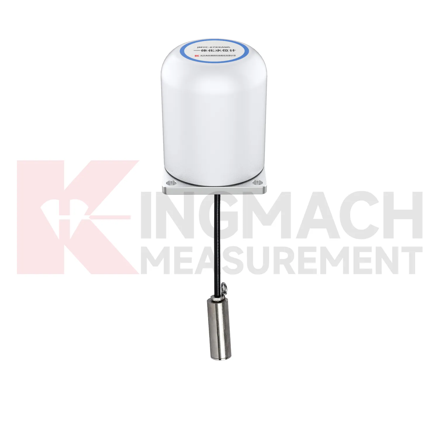
Future load cell cable maintenance will be shaped by long life assets such as dams, bridges, slopes, and transport corridors. Kingmach products that list 50 year design life, waterproof durability, temperature correction, and stored records are already moving in that direction. The next improvement is not just longer service life, but easier proof that the reading remains valid. Owners may require digital calibration files, sensor identity chips, maintenance timestamps, and platform records that survive system upgrades. MEMS sensors, vibrating wire sensors, and smart acquisition units may be used together, with each type assigned to the job it handles best. AI warning models can compare slow force drift with water level, temperature, rainfall, and movement data, but field checks will still matter. A low maintenance design should therefore include sealed connectors, stable cables, lightning protection planning, and clear calibration intervals. Future systems will be judged by how little uncertainty they leave during inspection.
Care & Maintenance of load cell cable
For load cell cable used in pile load testing, care begins before the first load step. Confirm that the selected solid load cell range, often between 1000 kN and 10000 kN on Kingmach listed models, exceeds the planned test load with proper margin. Check the 0.1 kN resolution, 0.5%FS precision, calibration certificate, bearing plate flatness, and centering arrangement. During the test, protect the cable from jack movement and keep the readout position safe from vibration and water. Record zero value, temperature, load stage, hold time, unloading stage, and any pause or adjustment. After the test, inspect the sensor for dents, side load marks, connector damage, and cable jacket cuts. Store the calibration coefficient with the test report, not only with the instrument box. If later readings appear inconsistent, compare them with jack pressure, settlement data, and loading procedure before blaming the sensor. Store the report with the test file.
Kingmach load cell cable
load cell cable is useful where the risk is not dramatic movement but slow, uneven load transfer. A bridge cable may relax in small steps, a support jack may settle after locking, a foundation pit strut may gain force overnight, and a dam anchor may respond to water level changes. Kingmach force monitoring products are designed for these long observation periods, with smart chips, temperature correction, waterproof structures, and compatible readouts or acquisition units across several models. The working value comes from repeatable measurement under real site conditions. That includes dust, water, vibration, long cable runs, tight installation space, and crews working around the instrument. A good record helps teams separate normal load fluctuation from a developing problem. It also reduces arguments during handover, because the reading is tied to a named point, a calibrated model, a timestamp, and the same measurement method used throughout the project. The result is a record that can survive handover between contractors and owners.
FAQ
Q: How can load cell cable be connected to a monitoring platform? A: Use compatible readouts, acquisition modules, data loggers, DTUs, and software platforms according to site access, cable distance, power, and reporting requirements. Q: What makes smart models useful in large networks? A: Stored model data, calibration coefficients, zero values, temperature data, and measurement records reduce confusion across many channels. Q: Should manual readings still be kept? A: Yes, manual checks are useful after installation, maintenance, abnormal alarms, or logger changes. Q: How should alarm limits be set? A: Base them on design stage, sensor range, expected load change, temperature behavior, and nearby monitoring points. Q: What data should be reviewed together with force? A: Settlement, displacement, tilt, water level, pore pressure, rainfall, temperature, construction events, and inspection notes.
Reviews
Andrew Lee
The visualization software is intuitive and powerful. It helps us analyze monitoring data efficiently.
James Thompson
The tiltmeters and accelerometers are very sensitive and provide precise data. Perfect for our structural health monitoring system.
Latest Inquiries
To protect the privacy of our buyers, only public service email domains like Gmail, Yahoo, and MSN will be displayed. Additionally, only a limited portion of the inquiry content will be shown.
Charlotte***@gmail.comUnited Arab Emirates
Hi, we require instrumentation cables suitable for harsh environments. Could you advise on specifica...
Ava***@gmail.comAustralia
Hi, I am looking for reliable tiltmeters and accelerometers for structural health monitoring. Please...
Related product categories
- load cell zero balance
- load cell connection diagram
- load cell recalibration
- load cell testing
- load cell wiring schematic
- calibration load cells
- calibration of load cell theory
- load cell failure
- load cell technology
- strain gauge load cell wiring
- diagram 4 wire load cell wire connection
- load cell accuracy calculation